


The purpose of this paper is to provide a rationale for the necessity of monitoring vibration in an IMU and the benefits of developping a Built-In Vibration Monitoring Feature.
Why monitoring vibration into an IMU ?
Those with experience of using an IMU (Micro-Electro-Mechanical Inertial Measurement Unit) in a harsh environment are aware of the need for careful consideration of vibrations and acoustics. MEMS sensors are based on internally vibrating mechanical elements. This has two main consequences:
- Performance degradation under vibration: Exposure to vibration can degrade IMU accuracy through what’s known as Vibration Rectification Error (VRE) or Vibration Rectification Coefficient (VRC). For high-precision applications such as surveying or dead reckoning, these errors can have a major impact.
- Resonance effects: Since the sensor itself vibrates, if the vibration frequencies of the vehicle match the sensor’s internal resonance frequencies, the IMU readings can become disturbed.
These effects are often key considerations during early design. Teams typically spend significant effort on complex simulations. These simulations only partially predict real-world behavior.
You must run expensive test campaigns using monitoring equipment. These tests validate the simulations. We have seen that even thorough simulations cannot fully replicate real-world conditions. Some customers have integrated our IMUs in harsher environments than designed. They endure up to 30 g RMS vibrations and 150 dB acoustics.
Adding an external monitoring device is good development practice. However, it is not perfect. It will never fully reflect the IMU’s actual experience:
- location of the measurement is offseted
- change of mass/setup forced by the external monitoring device will change result.
Introducing our built-in vibration monitoring feature
To address this, we have integrated an innovative vibration monitoring feature. It is directly in our IMUs and GNSS/INS. Our systems now provide real-time vibration analysis. This includes a full spectrum report and a synthetic report.
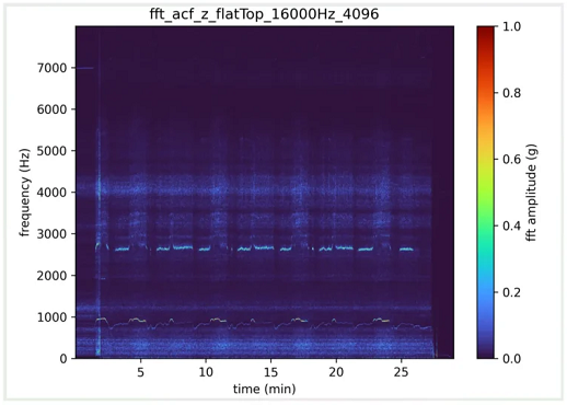
Full spectrum report
A complete FFT (Fast Fourier Transform) shows vibration amplitude across all frequencies. The following image corresponds to this full spectrum view. It shows the intensity of vibrations measured for each frequency over time.
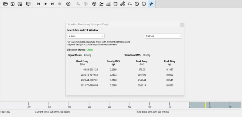
Simplified vibration report
A user-friendly summary dividing the spectrum into four frequency bands. For each band, the report provides overall vibration intensity (in g RMS), the dominant (peak) frequency, and its magnitude. The following image portraits a screen capture of the synthetic vibration report as displayed in our sbgCenter tool.
Technical characteristics
The built-in vibration monitoring module operates fully embedded within the IMU/INS, ensuring real-time performance without additional hardware. Its key specifications are:
- Bandwidth: up to 8 kHz (depending on the IMU model).
- Dynamic range: up to 40 g RMS (depending on the IMU model).
- Time synchronization: vibration reports are timestamped using the IMU clock for easy analysis.
- Fully embedded: all FFT computations are performed onboard.
- Update rate & resolution: vibration reports are generated every 0.25 s, with a 4Hz resolution.
- Window configuration: users can select from multiple FFT window modes — Flat Top, Hanning, or Rectangular with a variety of trade off between amplitude, accuracy and frequency leakage.
This lets you perform detailed vibration analysis at the IMU location. Users can correlate inertial noise and IMU performance with actual mechanical excitation. For example, real-time FFT data offers an additional metric. This complements the IMU’s Continuous Built-in Test (CBIT). It reveals mounting resonances or harmonic excitations. These coincide with changes in accelerometer noise or gyroscope bias.
Use cases of our built-in vibration monitoring feature
The Built-In Vibration Monitoring Feature can be used in many ways—and we expect our customers will find even more. Here are a few examples:
- Design-phase vibration analysis: During vehicle design, the feature helps optimize IMU mounting. Measuring vibrations directly at the IMU allows engineers to choose the best location, tune dampers, and design acoustic protection—without adding heavy or expensive external sensors.
- IMU Qualification on shakers: The vibration monitoring can be used during the qualification of an IMU or INS when subjecting them to vibrations (Random or sweep), allowing to confirm that the vibration measured match the vibration injected (transfer function) ; and can be used as a tool to discriminate whether a resonance is linked to the shaker, the setup or the IMU.
- UAV and Aerospace Systems: vibration monitoring can be used to detect resonance modes for rotorcraft or turbine engines and validate payload isolation when the IMU is mounted on a gimbal or stabilized platform.
- Ground Vehicles: Our INS are often used on ground vehicles for georeferencing (Mobile Mapping). The FFT can be used in innovative ways in this context: vibration data could be used to analyze road conditions or classify terrain types.
- Mission-related Built-In Test (BIT): In harsh operational environments, excessive vibration often indicates faults such as engine failure, gain control issues, or aerodynamic instability. The built-in monitor can detect these anomalies in real time, without the need for additional sensors.
- Structural Health and Modal Analysis: the FFT vibration data can be used to refine modal analysis—detecting shifts in resonant frequencies that indicate potential structural fatigue, loosening, or material degradation over time. This transforms the IMU into a dual-purpose sensor: both a motion tracker and a long term structural monitoring instrument.
Accessing the vibration monitoring feature
If your device is compatible, simply update to the latest firmware. Next, enable the vibration monitoring messages in the output configuration. To process the data:
1 – sbgCenter – visualize vibration reports easily.
2 – sbgBasicLogger – export data in ASCII format.
3 – sbgECom library – parse binary data quickly and efficiently.
Stay tuned for additional documentation and sample code to help you make the most of this feature.
Product Compatibility
This section details the specific products that currently support the Built-In Vibration Monitoring Feature. Compatibility depends on both the hardware revision and the installed firmware version. We’ve outlined the current requirements below to ensure you can utilize this functionality.
The vibration monitoring feature is currently available on:
- latest hardware revisions for the Ekinox Micro, Quanta Micro, Quanta Plus and Quanta Extra (INS) — running firmware version 5.5 or above
- Pulse-80 and Pulse-40 (IMUs) — running firmware version 2.0 or above
Please contact our support team if your product runs an earlier firmware version. They offer guidance on compatibility and upgrade options. This feature will be integrated into additional products in the near future.
For more information visit www.sbg-systems.com.


